Blower Shaft Alignment
Blower and Engine Shaft Alignment Procedure
1. Scope
The fluid coupler is already fitted on both shafts.
Shims under the 4 corners of the blower are added or removed to align the shafts. Do not move the engine.
2. Tools and Materials
Straight edge — rigid, minimum 127 mm (5 in)
Metal shims, various thicknesses
Torque wrench
Wrenches for the blower mounting bolts
Cleaning rags
3. Safety
The engine should be off.
4. Check Current Alignment
Check vertical alignment — top and bottom. Place the straight edge on top of both coupler halves, then on the bottom. It should rest flat on both halves in each position. If one side is higher, there will be a gap between the straight edge and the lower coupler half.
Check horizontal alignment — left and right. Place the straight edge on the left side of both coupler halves, then on the right side. Check for a gap in the same way.
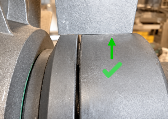
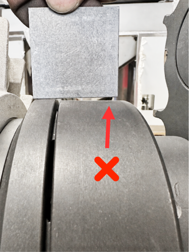
Measure the gap between the two coupler faces at all four positions: top, bottom, left, and right. The gap should be 2 mm at every position. If the gap is larger on one side, the shafts are not aligned correctly.

If the shafts are not aligned, proceed to the next section.
5. Alignment Procedure
Loosen all blower mounting bolts enough to change the shims. Keep the bolts in the holes.
Add or remove shims under the blower corners as needed. The shafts are correctly aligned when the straight edge rests flat on both coupler halves at all four positions, and the gap between the coupler faces is 2 mm at all four positions.
Tighten all blower mounting bolts to 30 lb·ft (41 Nm).
Check alignment again. Tightening the bolts can move the blower slightly. Using the straight edge, check vertical alignment at the top and bottom, and horizontal alignment at the left and right. Then measure the gap between the coupler faces at all four positions: top, bottom, left, and right. The gap should be 2 mm at every position.